House Wiring Diagrams and Project Guides
Wiring Diagrams for Light Switches- Numerous diagrams for light switches including: switch loop, dimmer, switched receptacles, a switch combo device, two light switches in one box and more.
Wiring Diagrams for Receptacle Wall Outlets- Diagrams for all types of household electrical outlets including: duplex, GFCI, 15, 20, 30, and 50amp receptacles.
Wiring Diagrams for 3-Way Switches- Diagrams for 3-way switch circuits including: with the light at the beginning, middle, and end, a 3-way dimmer, multiple lights, controlling a receptacle, and troubleshooting tips.
4 Way Switch Wiring Diagrams- Diagrams for 4-way switch circuits including: various source and light locations, dimmer for a 4-way circuits, wiring for 4 locations, and troubleshooting tips.
3 Way and 4 Way Switches to Control Multiple Lights- Diagrams for wiring to control multiple light fixtures with 3 and 4-way switches.
Wiring Diagrams for a Fan/Light Kit- Diagrams include: using a light switch to control both the fan and light, separate light dimmer and fan speed controls, light dimmer and pull chain fan, and an exhaust fan switch and timer.
Wiring Diagrams for Multiple Receptacles- Diagrams for wiring multiple receptacles including circuits for duplex receptacles and ground fault interrupters.
Guide to Electrical Wiring in your House
Electrical Wiring inside a house can seem like a very inexplicable thing. Wiring inside a newly constructed building can be easily installed. However, proper supervision must be taken to ensure that the wiring system is carefully established. This is a comprehensive guide to help homebuyers understand how wiring works inside a building
An “Electrical wire” refers to a material that channels electricity from a power source to electrical appliances inside a building such as the lights, fans, kitchen appliances, etc. Generally, large wire cables bring electricity into a structure and smaller wires distribute it evenly to all electrical plug points inside the building.
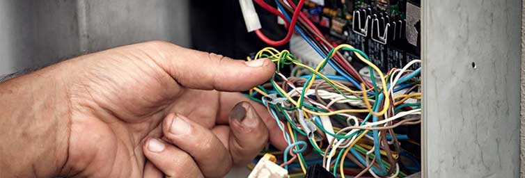
Defects in Electrical Wiring
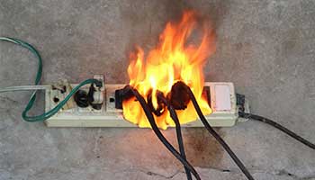
The quality of electrical products plays a major role regardless of whether it is for sockets, fittings or switches. Faulty material or improper fitting can cause sparks which can be dangerous and liable to ignition. Some of the defects in electrical circuits are:
Short circuit: A short circuit is the result of extremely low resistance between two conductors that supply the electricity in the path of the circuit. This ends up in excessive current flowing through and can cause the main power supply to be impaired. In such situations, the fuse is blown out. Improper insulation and loose wiring are causes for short circuit.
The human body is a good conductor of electricity. A single electric shock caused by faulty wiring can prove fatal and hence, certain measures must be taken to ensure that the safety of human beings is maintained. One of the first steps to ensure human safety is earthing the AC supply system of the building. There is a sufficient supply of earthing and all electrical gadgets and circuits should have an earth wire as it is necessary to null leakages in the circuit and prevent electric shocks.
Beginners Guide to Electrical Terminology
If you’re new to the industry, the language used can appear quite daunting at first. This guide looks at some key terms and phrases that you’ll be learning about and using during your electrical training with us
able – A cable is made up of one or more conductors and their insulated surrounding
Twin and Earth (1) – This is the most common cable used in domestic electrical installations, it is a flat grey thermo-plastic sheathed cable. Inside, it has two single conductors of the same size that are both separately insulated, one is brown in colour denoting its intended use as the line conductor, and the other is blue, denoting its intended use as the neutral conductor. A third un-insulated conductor sits between the two and this is used as the Circuit Protective Conductor or ‘earth’ as it is commonly known.
Flex (2) – A flexible cable that has a soft rubber or thermoplastic outer sheath and individually insulated conductors inside it. Each individual conductor is made up of very fine strands of copper to allow the cable to repeatedly flex.
SWA (3) – Steel Wire Armour, this is a cable that is surrounded by a layer of armour made up of steel wire, it is generally used where the cable requires a high degree of protection.
LSHF (4) – Low Smoke Halogen Free cable is a cable with a particular type of insulation that is designed so that it emits a small amount of smoke and zero halogen when exposed to fire or heat.
‘Singles’ (5) – A colloquial term used for when a cable is a self contained single conductor, can refer to any cable that is singular, however in a domestic setting PVC insulated singles are often what is mean by the use of the term.
Units of measurement
Ohms – An Ohm is the electrical unit used for measuring resistance, its symbol is Ω.
Watt – This is a unit of power and is denoted by use of the letter W.
Voltage – Voltage is the difference in electrical potential between two different points, it can be thought of as electrical pressure, and it is denoted by the letter V or U.
Amperes – This is the term used to describe the flow of electrical current, it is denoted by the letter A.
AC- Alternating Current is an electric current which reverses direction periodically. AC current is the way that electricity is distributed through the power network in the UK.
DC – Direct Current is an electric current that travels in only one direction, this is the type of current that a battery produces.
Circuit breaker (1) – A type of protective device for circuits, it will protect a circuit from overload and fault currents.
Fuse (2) – A fuse is a protective device. They are designed so that when more current is drawn through them than they are designed to take, a part of it melts, causing the circuit to become open and the electricity supply to become disconnected.
RCD – Residual Current Device, this is a type of device used to disconnect the electrical supply to a circuit, or bank of circuits in the event of a fault from line to earth. It does this by essentially monitoring the line and neutral currents. If there was a fault between line and earth, the RCD would trip as there would be no current on the neutral conductor.
There are three commonly encountered types:
RCCB (3) – Residual Current Circuit Breaker, what most people commonly refer to as an ‘RCD’, will often be found in a consumer unit protecting a bank of circuits.
RCBO (4) – Residual Current Circuit Breaker with Overload protection, this combines the function of an RCD and a circuit breaker in one device and can be found protecting one circuit.
SRCD – Socket Residual Current Device, as the name suggests this type of RCD is integral to a socket outlet.
Electrical Wiring Guide
In order to wire your own home, you must comply with the requirements of the 2020 edition of the National Electrical Code (NEC). The NEC is not intended as a design specification nor an instruction manual for untrained persons, its purpose is the practical safeguarding of persons and property from hazards arising from the use of electricity and addresses fundamental safety principles.
Electrical wiring
Electrical wiring is an electrical installation of cabling and associated devices such as switches, distribution boards, sockets, and light fittings in a structure. Wiring is subject to safety standards for design and installation. Allowable wire and cable types and sizes are specified according to the circuit operating voltage and electric current capability, with further restrictions on the environmental conditions, such as ambient temperature range, moisture levels, and exposure to sunlight and chemicals.
Associated circuit protection, control and distribution devices within a building’s wiring system are subject to voltage, current and functional specification. Wiring safety codes vary by locality, country or region. The International Electrotechnical Commission (IEC) is attempting to harmonise wiring standards amongst member countries, but significant variations in design and installation requirements still exist.
Wiring installation codes and regulations are intended to protect people and property from electrical shock and fire hazards. They are usually based on a model code (with or without local amendments) produced by a national or international standards organisation, such as the IEC.
commonly known as the “wiring rules”, specifies requirements for the selection and installation of electrical equipment, and the design and testing of such installations
attempt has been made to harmonise national wiring standards in an IEC standard, IEC 60364 Electrical Installations for Buildings. Hence national standards follow an identical system of sections and chapters. However, this standard is not written in such language that it can readily be adopted as a national wiring code. Neither is it designed for field use by electrical tradesmen and inspectors for testing compliance with national wiring standards. By contrast, national codes, such as the NEC or CSA C22.1, generally exemplify the common objectives of IEC 60364, but provide specific rules in a form that allows for guidance of those installing and inspecting electrical systems.
Colour coding of wiring by region
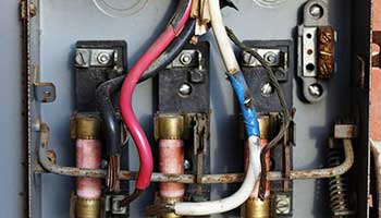
In a typical electrical code, some colour-coding of wires is mandatory. Many local rules and exceptions exist per country, state or region. Older installations vary in colour codes, and colours may fade with insulation exposure to heat, light and aging.
Materials for wiring interior electrical systems in buildings vary depending on:
Intended use and amount of power demand on the circuit
Type of occupancy and size of the building
National and local regulations
Environment in which the wiring must operate.
Wiring systems in a single family home or duplex, for example, are simple, with relatively low power requirements, infrequent changes to the building structure and layout, usually with dry, moderate temperature and non-corrosive environmental conditions. In a light commercial environment, more frequent wiring changes can be expected, large apparatus may be installed and special conditions of heat or moisture may apply. Heavy industries have more demanding wiring requirements, such as very large currents and higher voltages, frequent changes of equipment layout, corrosive, or wet or explosive atmospheres. In facilities that handle flammable gases or liquids, special rules may govern the installation and wiring of electrical equipment in hazardous areas.